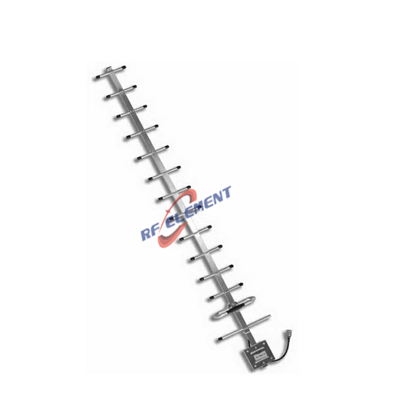
UHF Yagi Antenna: The Solutions for Long-Range Communication- Our Technological Leaps

In the realm of wireless communication, UHF Yagi antennas are renowned for their directional precision, high gain, and reliability in transmitting and receiving signals over long distances. Operating in the Ultra-High Frequency (UHF) range (300 MHz to 3 GHz), these antennas are indispensable for applications requiring focused signal coverage, from television broadcasting to emergency communication systems. RF element, a leader in advanced RF solutions, designs low-PIM UHF Yagi antennas that combine rugged durability with cutting-edge performance, ensuring seamless connectivity in even the most challenging environments.
This guide explores:
Technical advantages of RF element UHF Yagi antennas.
Applications in broadcasting, public safety, and amateur radio.
Installation best practices and real-world use cases.
Why RF element UHF Yagi Antennas Excel
1. High Gain and Directional Accuracy
Gain: 10–15 dBi, enabling long-range communication up to 50 km under optimal conditions.
Narrow Beamwidth: Focused radiation patterns reduce interference from adjacent signals.
Front-to-Back Ratio: >20 dB minimizes rearward signal pickup for enhanced clarity.
2. Wide Frequency Coverage
RF element UHF Yagi antennas support critical bands, including:
TV Broadcasting: 470–862 MHz (UHF TV channels 14–69).
Public Safety: 400–520 MHz (emergency services, police, fire departments).
Amateur Radio: 430–450 MHz (HAM radio enthusiasts).
3. Durability for Outdoor Use
Weatherproof Construction: Aluminum alloy elements and fiberglass booms withstand wind speeds up to 150 mph.
Corrosion Resistance: Powder-coated finishes and stainless steel hardware ensure longevity in coastal or humid environments.
Temperature Range: Operates in -40°C to +85°C, ideal for extreme climates.
Technical Specifications of RF Element’s UHF Yagi Antennas
| Model | Frequency Range | Gain (dBi) | Beamwidth | Polarization | Connector Type |
|---|---|---|---|---|---|
| RFE-YAGI-800 | 700–900 MHz | 12 | 30° | Horizontal | N-Female |
| RFE-YAGI-500 | 400–520 MHz | 10 | 45° | Vertical | SO-239 |
| RFE-YAGI-600 | 600–800 MHz | 14 | 25° | Horizontal | N-Female |
Applications of UHF Yagi Antennas
1. Television and Radio Broadcasting
Signal Boosting: Extend coverage for UHF TV channels in rural or mountainous regions.
Translator Stations: Relay signals between broadcast towers and remote communities.
2. Public Safety and Emergency Communication
Disaster Response: Establish temporary communication links during wildfires, floods, or earthquakes.
Law Enforcement: Secure point-to-point communication for tactical operations.
3. Amateur Radio and Wireless Networking
HAM Radio: Enable long-distance communication (DXing) on 70 cm bands.
Wi-Fi Backhaul: Connect remote locations using UHF frequencies for low-latency data transfer.
Installation and Optimization Guide
1. Site Selection and Alignment
Line-of-Sight: Mount antennas on rooftops, towers, or hills to avoid obstructions.
Directional Alignment: Use a compass or GPS to point the antenna toward the signal source (e.g., broadcast tower).
2. Cable and Connector Management
Low-Loss Coaxial Cables: RG-8X or LMR400 reduces signal attenuation over long runs.
Lightning Protection: Install surge arrestors and grounding kits to prevent damage from electrical surges.
3. Performance Testing
VSWR Measurement: Ensure a Voltage Standing Wave Ratio (VSWR) <1.5:1 for optimal efficiency.
Field Strength Testing: Validate signal strength at the receiver using tools like a spectrum analyzer.
Case Study: Rural TV Broadcasting Network
A Southeast Asian broadcaster deployed RF element RFE-YAGI-800 antennas to expand UHF TV coverage to remote villages. Results included:
70% Coverage Increase: Reached 50+ previously underserved communities.
30% Cost Savings: Reduced reliance on satellite links through direct tower-to-tower communication.
FAQs About UHF Yagi Antennas
Q: Can UHF Yagi antennas receive VHF signals?
A: No—Yagi antennas are frequency-specific. For VHF coverage, consider a dual-band VHF/UHF model.
Q: How to adjust the antenna for maximum gain?
A: Fine-tune the azimuth (horizontal) and elevation angles using a signal strength meter.
Q: What maintenance is required for outdoor installations?
A: Inspect elements for physical damage annually and tighten bolts to prevent wind-induced misalignment.
Why Partner with RF element?
Custom Designs: Tailored frequency ranges, element counts, and mounting solutions.
Global Certifications: FCC, CE, and RoHS compliance for international deployments.
Technical Support: 24/7 assistance for installation, troubleshooting, and optimization.
RF element UHF Yagi antennas are engineered to deliver unmatched directional performance, durability, and versatility for critical communication needs. Whether enhancing broadcast networks, supporting emergency services, or enabling amateur radio, our solutions ensure reliable connectivity over vast distances.
Explore RF element’s Solutions →UHF Yagi Antenna
TAG:UHF Yagi Antenna: The Solutions for Long-Range Communication https://www.rfelement.com

