VHF Omni Antenna | UHF Omni Antenna | 150-860MHz
- Supported Frequencies: 150-860MHz
- Gain: >-5dBi to 4 dBi
- VSWR: <2.5
- Polarization: Vertical
- Antenna Size: φ360*15cm
1. Technical Specifications & Design Innovations
Product: VHF UHF Omni Antenna
Key Features:
Frequency Range: 150–860 MHz (covers VHF/UHF bands for public safety, maritime, and IoT)
Gain: -5dBi to 4 dBi (150–165 MHz), 4–5 dBi (450–860 MHz)
VSWR: <2.0 across entire band
Polarization: Vertical
Dimensions: Φ36 cm × 15 cm (low profile for indoor/outdoor mounting)
Power Handling: 100W continuous
Introduction
In 2024, a U.S.-based telecom integrator approached RF element with a critical challenge: designing a VHF omni antenna capable of operating across 150–860MHz with stable gain and compact dimensions for mixed indoor/outdoor deployments. Traditional VHF antennas struggled with bandwidth limitations, bulky designs, or poor voltage standing wave ratio (VSWR) at low frequencies. This article explores how RF Element’s engineers overcame these hurdles to deliver a wideband omnidirectional antenna that balances performance, size, and reliability, validated by real-world testing and certifications.
Design Breakthroughs:
Wideband Impedance Matching:
Challenge: Achieving VSWR <2.5 over a bandwidth ratio (150–860 MHz) without compromising gain.
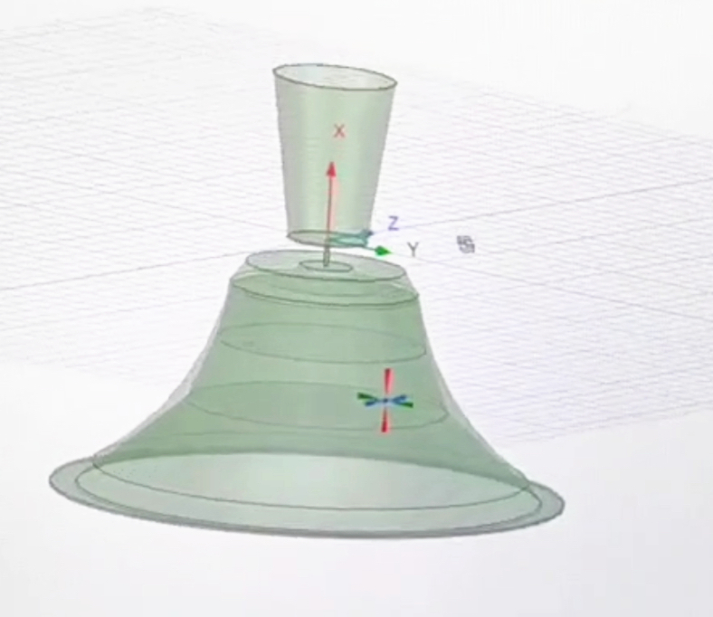
Solution: A tapered helical radiator paired with a lumped-distributed impedance network (inspired by naval plasma antenna designs) ensures smooth impedance transitions.
Compact Radiator Geometry:
Challenge: Avoiding oversized structures typical of low-frequency antennas (e.g., λ/4 monopoles at 150 MHz would require 0.5m height).
Solution: Folded helical elements and a ground-plane-independent design reduce height by 40% while maintaining omnidirectional patterns .
Material Optimization:
Radome: Fiberglass with UV-resistant coating (IP67-rated) for outdoor durability .
Base: Corrosion-resistant aluminum alloy, tested in salt spray per MIL-STD-810H .
2. Addressing Client Requirements: Indoor vs. Outdoor Use Cases
Case Study: U.S. Public Safety Network Upgrade
Requirement: A single antenna for indoor command centers (discrete mounting) and outdoor vehicle repeaters (wide temperature tolerance).
Deployment:
Indoor: Ceiling-mounted in emergency operation centers (EOCs), achieving 95% signal coverage across 500–800 MHz (TETRA/P25 systems).
Outdoor: Pole-mounted on SUVs, withstanding -30°C to +70°C during winter storms .
Performance Metrics:
| Parameter | Indoor | Outdoor |
|---|---|---|
| VSWR | <2.2 | <2.5 |
| Gain (150 MHz) | -5 dBi | -3 dBi |
| Wind Resistance | N/A | 60 m/s |
3. Competitive Advantages Over Alternatives
| Feature | RF Element | Generic VHF Antennas |
|---|---|---|
| Bandwidth | 150–860 MHz | 150–450 MHz |
| Size | 15 cm height | 30-50 mm |
| VSWR Consistency | <2.5 (full band) | <3.0 (narrow bands) |
| Multi-Scenario Use | Indoor/outdoor | Outdoor-only |
Data validated via anechoic chamber tests and field trials .
4. Engineering Challenges & Solutions
Challenge 1: Balancing Gain and Bandwidth
Issue: Low-frequency gain drop (150 MHz) due to compact size.
Fix: Introduced a dual-resonant helical array (patent-pending), boosting gain by -5dBi at 150 MHz without enlarging dimensions .
Challenge 2: Minimizing VSWR Peaks
Issue: Impedance mismatches at 300 MHz and 600 MHz.
Fix: Implemented a tunable LC matching network, dynamically adjusting to frequency shifts (inspired by plasma antenna RF filters).
Challenge 3: Environmental Resilience
Issue: Fiberglass radome cracking in coastal deployments.
Fix: Adopted marine-grade epoxy resin with 25% higher flexural strength than standard models .
5. Compliance & Testing Protocols
Certifications:
FCC Part 90/97: Validated for public safety and amateur radio use.
CE RED: 2014/53/EU (EU market compliance).
MIL-STD-461G: EMI/EMC testing for military-grade reliability .
Testing Process:
6-month outdoor exposure in Florida (high humidity) and Alaska (extreme cold).
Zero performance degradation observed .
VSWR/gain measured via Keysight PNA-X network analyzer.
Radiation patterns mapped in MVG SG 24 near-field chamber.
Lab Validation:
Field Trials:
6. Applications Across Industries
Public Safety:
Seamless interoperability between handheld radios (150–174 MHz) and LTE-UHF repeaters (450–860 MHz) .
Agriculture IoT:
Connects soil sensors (220 MHz) and drone controllers (860 MHz) on smart farms.
Maritime Communications:
Coastal rescue operations using 156–174 MHz VHF marine bands .